GNSS - Determine Coordinate System using Multiple Points
GNSS-Determine-Coordinate-System-using-Multiple-Points.pdf
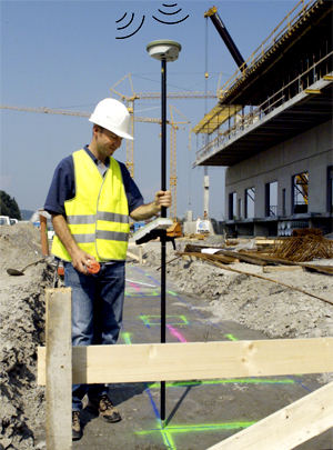
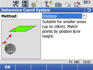
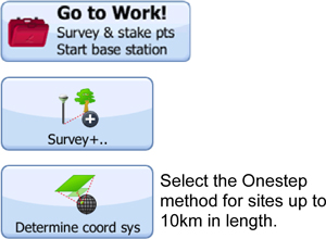
This guide is designed to enable the user to create a co-ordinate system on System Viva, for a site which already has a local grid system in place, having existing points with known co-ordinates able to be surveyed with the GPS sensor, typically survey control stations. It is based upon a ‘One-Step’ method which is suitable for sites up to 10km in length.
Enter the site control points into a job as fixpoints.
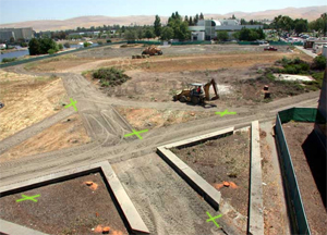
Go out and measure the stations in WGS84, naming the stations the same as for the entered fixpoints.
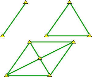
2 points allows for a local orientation
3 points create a plane surface & orientation
4+ points creates &apm; checks the surface.
First, create a new working job (BATH) where the measured points will be stored. This can use either OSGB36 or WGS-84 as the coordi-nate system, it doesn't matter. All points are stored as WGS-84 by default. go out and measure all the points, taking repeated shots to ensure a robust solution.
Second, create a new job for the local coordinates (BATH LOCAL CTRL), and enter the Eastings/Northings/Ortho-Heights for the given control stations.
Ensure point ID’s are the same.
1
2
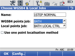
Input a name for the Coordinate system to be created. Since the coordinate system will be site specific, it is recommended to incorporate the site name, eg <SITE NAME> LOCAL SYSTEM.
For matching multiple points, leave the button unchecked. Select or define the job in which the GPS surveyed points are stored (WGS84 Points Job) and the job in which the local grid coordinated points are stored. If you can’t find the job by scrolling through, then press Enter to change the storage device.
3
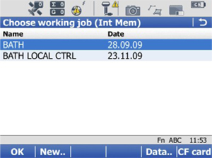
The job location is shown in the blue location bar, in this case Int Mem. F6 allows the user to toggle between CF card, USB stick, SD card to locate your job. Alternatively a new job can be created using F2 <New..>. Job data can be viewed using F5 <Data..>, and new points can be added here also if required. Press <OK> to continue.
4
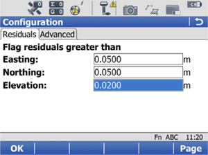
Pressing F2 <Config..> will let you define the size of residuals to be flagged. Press <OK> to continue.
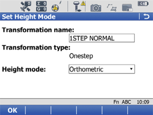
5
Set height mode. If a local height datum is being used, set this to Orthometric. If a Geoid model is to be used, set to Ellipsoidal. Press <OK> to continue.
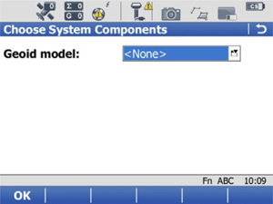
6
If a Geoid model is to be used, select it here i.e. OSGM02 or a site specific “x.GEM” file. Press <OK> to continue.
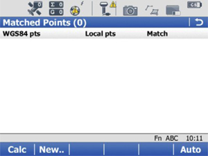
7
This is where GPS surveyed points are matched to the corresponding point with known local grid coordinates. Press F2 <New..> to add points one by one. *Note: If the WGS84 job and local job have identical point ID’s, then F6 <Auto> will match these automatically.
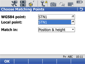
8
Select the point ID’s to be matched. With WGS84 Point highlighted, pressing enter will give the user the opportunity to survey a position at this time. With Local Point highlighted, pressing enter will give the user the opportunity to create/input new local coordinated points.
Select the elements to be matched, e.g. height only for site datum mark. Press <OK> to continue.
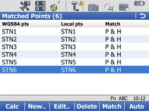
9
Continue until all your points are matched. <Edit..> to make any changes to the points, <Delete> to remove the points from the solution, <Match> to toggle through the Matched elements (e.g. Pos. & Ht., Pos Only, Ht. Only).
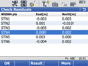
10
The calculated residuals are displayed. The highest residual for each element is flagged, along with any which exceed the limits set in step 1.3. Press F4 <More> to view the height element. If any changes need to be made, then press the back button to return to the match screen. If the residuals are satisfactory, F3 <result> to view the transformation results (see x ), or F1 <OK> to store the coordinate system (go to x).
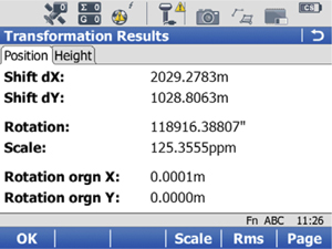
11
This screen shows the transformation parameters.
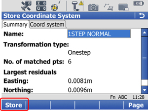
12
A summary is displayed, and if the user wishes residuals to be distributed using a particular method, this can be defined in the Coord system tab. Otherwise press F1 <Store> to store the new coordinate system, attach it to the WGS84 job and return to the main menu.